FAQ - Clutch
If you can find the same part somewhere else for cheaper simply send us the details and we’ll beat the price by 10%. Email [email protected] for more details or see our terms and conditions.
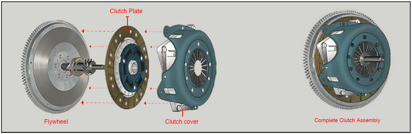
The simplest way is to think of two sides.
One side is the vice that is the flywheel and cover assembly. They are both connected to the crank shaft. They turn together, carrying the engine torque, and work together to clamp onto the clutch
plate.
The second side is the assembly consisting of the clutch plate and gearbox input shaft. When keyed together, the clutch plate and gearbox input shaft will always turn together.
When the flywheel and cover assembly clamp onto the clutch plate:
• The friction material grabs,
• The clutch plate and gearbox input shaft start spinning at the same speed as the flywheel,
• The torque (turning motion of the engine crank) is delivered to the gearbox via the clutch plate and input shaft, allowing the wheels to turn.
When the clutch pedal is engaged (pushed down), the actuation system works on the spring loaded part of the cover assembly. It winds back the vice and there is no clamp on the clutch plate, it stops
turning and torque is disconnected.
When the clutch pedal is disengaged the vice tightens again enabling the car to continue.
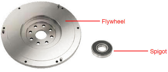
Flywheel
The flywheel is one side of the vice. It is a big metal disc that bolts directly to the crankshaft. Its role is to:• Provide a flat clamping surface for the clutch plate to match.
• Keep momentum. It is a heavy mass that keeps turning the crank.
• Take heat away from the clutch plate.
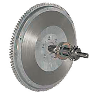
Because the flywheel is bolted directly to the crank, the flywheel will always spin at the same rate as the crank shaft of the engine. (Around the outside of the flywheel there is a ring gear. Although it is a part of the flywheel, ring gears have nothing to do with the clutch itself.
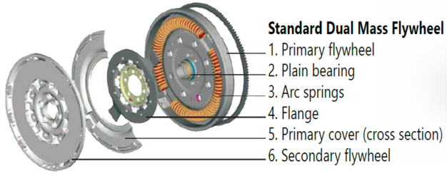
Some modern vehicles come fitted with Dual Mass Flywheels (DMF), more details about this can be found in the dual mass section of the FAQ).
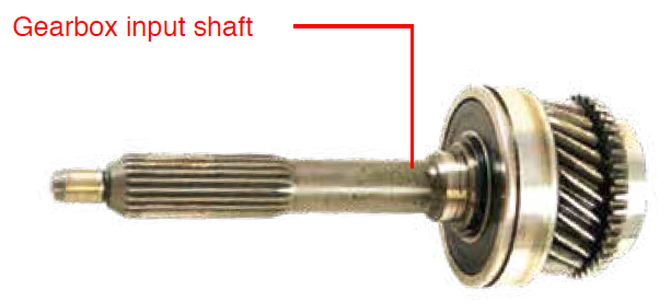
Gearbox input shaft
A small but very strong shaft. At one end is a locating pin that sits in the centre of the flywheel/crank. A spigot bearing sits in the centre of the flywheel, on the locating pin of the shaft. Because the input shaft is not bolted to the crank, it does not turn with the crank, it just uses it as a locating point.The opposite end of the shaft is connected to the gearbox. Along the shaft you’ll find gear teeth, called the spline, that match the centre hole of the clutch plate.
The gearbox input shaft’s purpose is to:
• Line up the gearbox with the centre of the crank shaft, keeping the rest of the drive train straight and true to the crank.
• Give the clutch plate a direction to locate onto and position itself.
Clutch Plate/Disc
The clutch plate is a disc that slides over the gearbox shaft. The spline or teeth at the centre of the clutch plate match the teeth of the gearbox input shaft. When the clutch plate slides over the shaft, the matching spline teeth mean the clutch plate is keyed or locked into the gearbox input shaft, and is positioned flat to the flywheel.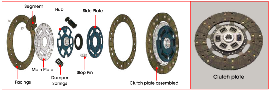
Around the outside of the clutch plate, on both sides, there is a hoop of friction material. The friction material riveted to the disc is designed to grip the flywheel. Because of the interlocking spline, the clutch plate and gearbox input shaft will then turn together.
‘When things rub together friction comes into play. In some cases you don’t want friction, so a lubricant is used. In other cases you want the friction and use materials to maximise it to achieve grip. Examples of friction material include brake pads, tyres and the material on clutch plates.’
Friction material
Friction material is on either side of the clutch plate. Organic material is dark in colour and feels progressive as it is clamped. Ceramic material is generally in the shape of buttons and grips quickly, making it a slightly harsher than organic material.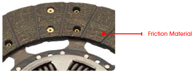
Cushioning
The term cushion is used to describe the effect of the segments placed between the friction material. They are a type of wave washer that “cushions” the clamping force as it is applied. By cushioning the clamping force it feels progressive and smooth for the driver.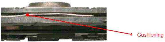
Dampening
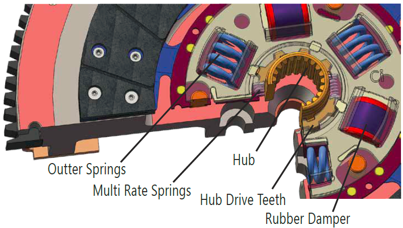
The springs in the centre of the clutch plate absorb the pulsations of the engine. They “dampen” out the vibration and provide a progressive take up of the torque.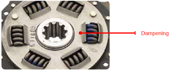
The type of friction material, cushioning and dampening used in a clutch plate has a big impact on how comfortable the clutch is to use. Taking these measures out will provide a quicker take up of torque, but the trade-off is a less comfortable drive. Consequently, race style clutches are very harsh to use, but transmit torque quickly.
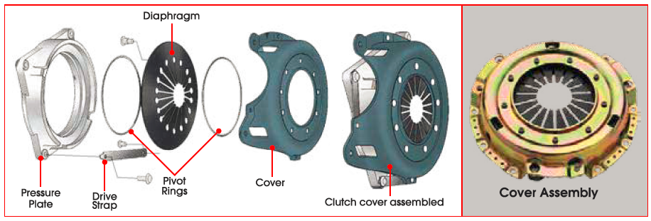
Cover Assembly
The cover assembly bolts onto the flywheel and OVER the clutch plate. The purpose of the cover assembly is to carry the matching surface (a heavy metal casting) for the flywheel, and a spring loaded system that pushes the casting towards the flywheel. Together the cover assembly and flywheel work just like a vice and work together to clamp down onto the friction material of the clutch plate. When the cover is bolted to the flywheel, its default position is clamped. The vice is tightly clamped onto the clutch plate.
Actuation System
To disconnect the clutch, or let go of the torque, there is an actuation system which begins at the pedal and ends at the clutch cover assembly.
Engaging the clutch pedal is the same as winding back one side of the vice. When the clutch pedal is pushed, it will works a series of connected parts that ends with a push onto the spring loaded part of the cover assembly. The spring load is taken off and because the clutch plate is no longer clamped to the flywheel, it will stop spinning at the same rate as the crank. It means you have disconnected drive. Remember the locating pin of the gearbox input shaft is just a locating pin. It will sit in the flywheel, but is not bolted to it so it will not spin at the same rate.
Bearing
The bearing is fixed to the clutch fork on one side and has a surface which spins on the other. As the bearing is pushed onto the cover the surface spins, minimising the stresses and strains on the two parts.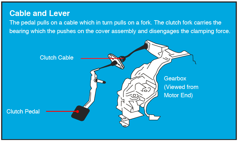
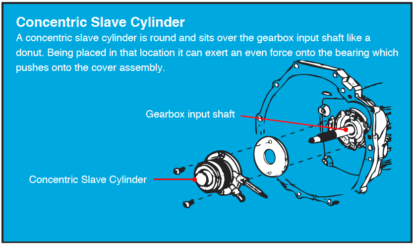
Hydraulics
More recently hydraulics have been used for actuation systems. A hydraulic system adds a clutch master and slave to the actuation system. Instead of a cable, the pedal acts on the Master cylinder which increases pressure in a line. The increased pressure activates a slave cylinder which pushes onto the bearing and activates the clutch.
It's time to replace the clutch when Flywheel and Cover Assembly spin at a different rate to the clutch plate/disc and gearbox assembly. When the clutch plate/disc is clamped, there’s a moment of friction while the clutch plate/disc material begins to grip, and everything connects.
That moment generates a lot of heat, which affects the friction surfaces. A clutch is a friction coupling, and friction wears out surfaces. Overtime the clutch plate will lose material and the surface of the flywheel will become uneven.
As the friction surfaces change, the grip drops and the clutch begins to slip. It will not clutch or grab as much torque, which is when it is time to replace the clutch. It will present as a slipping or shuddering clutch.
How long that takes depends on how it’s used. Things like driving hard, towing heavy loads or driving with your foot resting on the clutch pedal creates more heat, bringing clutch replacement forward.
If driven carefully, a clutch will have a long life.
Consider this. Car engines create 50% more power on average than they did 20 years ago while the surface area of the clutch plate and flywheel remains relatively unchanged. It has never been more important that the mating surfaces of the clutch plate and flywheel are maintained to keep up with the ever-increasing power of the modern engine.
Of particular importance to the performance of the clutch is the condition of the flywheel surface. The repeated release and clamp of the clutch plate on the flywheel can generate heat in excess of 750°C at its surface, altering the surface microstructure from the original cast iron.
Combined with repeated cycles of heating, cooling and abrasion, the tiny asperities (or ridges) that contribute to the friction characteristics of the flywheel become smoothed out (glazed) and the performance of the clutch starts to be affected. To return the flywheel to a perfectly flat cast iron surface with a high friction coefficient, the flywheel must be ground down in a highly precise manner.
When using a grinding machine, there are several recommendations that specialist clutch workshops make.
- Dowell pins used to positively locate the flywheel to the clutch cover plate should be removed from the flywheel. Once the flywheel is machined, new dowell pins should be used in replacement.
- In the case of a stepped or recessed flywheel, the geometrical relationship of the two surface levels must remain identical. Thus, even if one surface appears unaffected by surface glazing, both must be ground down equally.
A Dual Mass Flywheel (DMF) is comprised of two flywheels that work together with dampening springs to reduce vibrations.
Advantages
- Isolates engine vibrations- Reduces noise
- Helps to prevent transmission damage
- Improves shifting comfort
Dual Mass Flywheel Replacements (DMR) also known as a Solid Mass Flywheel (SMF) move the damping system from the flywheel to the clutch plate. This returns the flywheel back to a conventional solid mass flywheel.
Advantages (over DMF)
- Greater reliability
- Better thermal dynamics
- Cost efficient: Both on the initial purchase and ongoing with the ability to machine the flywheel.
Note: When a DMR system is fitted can have an increase in drive train noise.
- Getting it right the first time. It is vital to diagnose the cause of clutch malfunction before clutch replacement, i.e. check hydraulic system - bearing free travel - clutch cable, oil leaks and check for any signs of red dust when old clutch is being removed. Any or all of these problems must be corrected before installing a new clutch.
- Ensure clutch supplied is correct for the application. Use the online catalogue or if you’re unsure contact our customer service for further clarification.
- Flywheel must be replaced or machined or the clutch warranty will be void. Inspect the spigot bearing or the pilot bush and replace if necessary.
- Before fitting, check the clutch for any shipping damage. Next clean the gearbox main drive shaft splines, then check that clutch disc slides freely on the shaft. Lightly grease the shaft splines with high temperature grease, do not over grease as this can contaminate the clutch plate/disc. Always ensure bell housing is degreased and is free of any dust and that fibres from the worn clutch are removed.
- Check clutch release fork for cracks, check the clutch cable for stretch signs and check the release bearing guide tube for any wear. Always lightly grease the outside diameter of the tube. This will allow smooth sliding of the bearing carrier. Always check bearing on clutch release fork after installing the bearing on it. Move the fork forwards and backwards i.e. in both directions, to ensure bearing is secure and does not fall on any part (clutch fork or bell housing) before refitting gear box.
- Place the clutch cover pressure plate assembly over the clutch disc, after checking that the disc is the right way around and the hub section of the disc does not fall on the casting of the clutch cover assembly or the flywheel. A suitable clutch aligning tool will ensure correct alignment, assist in ease of installation and avoid spline damage. Ensure pressure plate dowels are aligned to the cover. Tighten bolts in a diagonal pattern and never use air tools to install a clutch cover assembly, bolts should be torqued to the manufacturer’s specification. Torquing down bolts in an uneven pattern in some instances could cause the lever strut to dislodge itself from the pressure plate casting.
- When the pressure plate has been torqued down securely to the flywheel, ensure that the diaphragm tips (in the case of a lever type cover assembly, the release lever tips) are in a parallel or slightly upward position and do not go over centre of the parallel position.
- Refit gearbox, taking care not to bend the clutch disc. Never hang the gearbox off the clutch disc or use any force to align gearbox shaft.
- Check all bell housing dowels are in correct position and tighten bell housing bolts. Ensure there is no dirt or foreign material between the mating surfaces of the engine and the bell housing.
- Perform any clutch adjustments to vehicle manufacturer's specifications and always reset the clutch master cylinder push rod to obtain comfortable pedal release position (clutch taking up as close as possible to the floor prevents clutch shudder and in most cases preferred by vehicle drivers). Keep in mind that the diaphragm tip position has changed with the installation of the new clutch.
- Always check the clutch cable if you are unable to obtain disengagement when a new clutch is fitted. Start off your checking process by replacing the cable. If it is a hydraulic clutch start by checking the clutch master cylinder and the clutch slave cylinder, ensuring there is no air in the system and nothing blocking the compensating port. This is essential to obtain maximum travel for disengagement.
- Road test vehicle and never abuse a newly fitted clutch.
The Mantic twin and triple track system does require some unique steps when installing the system compared to a standard single plate/disc system. A copy of the installation guide can be found below.
DownloadIt is important to troubleshoot any faults before replacing the clutch system. Below is a troubleshooting guide for the common faults that occur with clutch systems.
Download GuideFAQ – Ordering and Delivery
Content will placed in soon...
No, we cannot deliver to PO Boxes. All orders must be signed for so we recommend putting a business address as the delivery address to avoid any delays.
FAQ – Returns and Warranty
If it’s in a sellable condition and providing you’ve purchased it within 30 days you can send it back to us for a full refund. Simply email us at [email protected]
Depending on the clutch brand you purchased depends on the warranty period. To find out more please find our warranty conditions
hereWe would recommend firstly looking at the Troubleshooting guide in the Clutch section of the FAQ. You can also email our technical department at [email protected] and we might be able to help before you remove the clutch. If the clutch is still within the warranty period and you wish to make a claim you can do this by contacting us at [email protected]
If the clutch is still within the warranty period and you wish to make a claim you can fill out the form below; email a copy (with any supporting documents) to [email protected] and attach a copy of it with the product when you post it back to us.
Once we receive the return our technical team will assess the claim and will respond within 10 business days. For our full terms and conditions regarding warranties please refer to the link below: WARRANTY STATEMENT